A different way to use an IR sensor and the Arduino microcontroller to measure infrared pulses/signals
 |
| Arduino UNO - like microcontroller |
With a microcontroller board like the Arduino UNO and a simple infrared light sensor you can read the signals and used pulse sequences from an IR remote control. Probably you've been looking at this website from adafruit.com already, so did I at the beginning. But I didn't want to believe that bypassing the board and using cryptic byte-commands is the only way to measure short pulses in the range of few microseconds, and in the following I will show you how to do the pulse measuring in a more understandable yet potentially more precise way. Among others we use the pulseIn() and the micros() function. See how to use the resulting pulse sequence to control IR equipment in this following article. If you want to control your arduino with an available IR remote, check this blogpost.
Let's first have a look at the code first, afterwards we'll discuss and explain it.
// THIS CODE WAS IMPLEMENTED BY PATRICK BAYER IN THE YEAR 2014. DO NOT CLAIM THIS CODE FOR YOUR OWN IN ANY WAY AND QUOTE THE SOURCE WHEN YOU USE IT.
#define messart 2 // Matrix x-values
#define valuepairs 100 // Matrix y-values -> should be bigger than amount of sent pulse-pairs by IR-remote; setting the value higher should not bring problems.
int measuremethod1 = LOW; // if value is LOW, pulseIn() waits for the pin to go LOW, starts timing, then waits for the pin to go HIGH and stops timing.
int measuremethod2 = HIGH; // if value is HIGH, pulseIn() waits for the pin to go HIGH, starts timing, then waits for the pin to go LOW and stops timing.
// pulseIn() returns 0 if no pulse starts within a specified time out !!!
int measureoutput; // placeholder for serial output
int irpin=2; // IR Sensor position on Arduino
int i; // used for different loops; can theoretically be implemented in the loops directly
long matrix[valuepairs][messart]; // definition of the matrix
int ende; // variable integer for ending, cause matrix is normally not filled totally
int changemethods=1; // starting mode; in the loop sequence always HIGH,LOW,HIGH,LOW,... measure
int sm=10; // round, for example on full hundreds, for this sm = 100
void setup () { Serial.begin(9600); }
long roundvalues(long rundwert){if(rundwert-rundwert/sm*sm>(sm/2)){return(rundwert/sm*sm+sm);}else{return(rundwert/sm*sm);}} // function to round values in the output
void loop(){
ende=valuepairs; // for resetting
if(changemethods==1) {
for(i=0;i<valuepairs;i++) {
matrix[i][0]=pulseIn(irpin, measuremethod1);
matrix[i][1]=micros();
if(matrix[i][0]==0){ende=i; i=valuepairs; if(matrix[0][0]>1){changemethods=0;}} }
measureoutput=measuremethod1; }
else {
for(i=0;i<valuepairs;i++) {
matrix[i][0]=pulseIn(irpin, measuremethod2);
matrix[i][1]=micros();
if(matrix[i][0]==0){ende=i; i=valuepairs; if(matrix[0][0]>1){changemethods=1;}} }
measureoutput=measuremethod2; }
if(ende>0) {
if(measureoutput==0){Serial.println("-------- New record: --------");Serial.println(); Serial.println("| ON | OFF | (whereby OFF was calculated with the micros() command)");Serial.println();}
else {Serial.println("-------- New record: --------");Serial.println(); Serial.println("| OFF | ON | (whereby ON was calculated with the micros() command)");Serial.println();}
for(i=0;i<ende;i++) {
Serial.print(matrix[i][0]);
Serial.print(",");
Serial.print(matrix[i+1][1]-matrix[i][1]-matrix[i+1][0]);
Serial.print(",");
Serial.println(); }
Serial.print(" Listing has ended, amount of pairs: ");Serial.println(ende);
Serial.print(" CSV: ");
for(i=0;i<ende;i++) {
Serial.print(matrix[i][0]);
Serial.print(",");
Serial.print(matrix[i+1][1]-matrix[i][1]-matrix[i+1][0]);
Serial.print(","); }
Serial.println();
Serial.print(" CSV smooth: ");
for(i=0;i<ende;i++) {
Serial.print(roundvalues(matrix[i][0]));
Serial.print(",");
Serial.print(roundvalues(matrix[i+1][1]-matrix[i][1]-matrix[i+1][0]));
Serial.print(","); }
Serial.println();
Serial.print(" Method for measuring: (1=HIGH, 0=LOW):"); Serial.println(measureoutput);
Serial.println(); }
}
 |
| Screenshot of the output |
On the right you see a screenshot of the serial output, to see how a measured pulse signal actually looks like. Click the image to enlarge it.
IR sensors can have a different allocation of output pins, so installing it on your Arduino relies on you. In many cases, this sensor outputs a high value (5V) when no IR signal is received, so a pulse of the remote is related to a low voltage on the receiving-pin, as shown in the pulse scheme later. This sensor outputs a low voltage when receiving a 38 kHz signal, what means the infrared LED in your remote goes for about 13 microseconds and out for about 13 microseconds, and this loops for e.g. 800 microseconds. These 800 microseconds are then one "pulse" as shown in the pulse scheme afterwards. So we do not measure those very little 38 kHz pulses with the Arduino, because this is done by the sensor itself. For more information visit this page, where you can see pictures of oscilloscope measurements on the topic of IR proximity detection.
The program is beginning with defining different integers, whereby this section is very well explained in the code itself. Maybe you wonder why some integers are defined using the method #define. Look at this explanation for further information on this topic.
In a first step we have a function called roundvalues, we use long and not int for this because sometimes quite high times (f.ex. 40000 us, where us means microseconds) are in use, and with int we get a roll over - look here if you're interested why. So with roundvalues we can round the output pulse lengths - and they look more smoothly afterwards.
One basic problem stated on the adafruit page on the topic of reading IR signals was that digitalRead () is too slow for our purpose, and this is quite correct. But instead of measuring the time a certain pulse is high or low, a good idea is to measure the pulse length itself using the pulseIn() function. So one possibility would be to say pulseIn(irpin,HIGH) and afterwards pulseIn(irpin, LOW) and save the different times. But this is not what I did in the code above, for a good reason: pulseIn(irpin, HIGH) for example waits for a pulse to go high (so to 5V on the pin) and measures the time this high pulse is active in microseconds, up so several seconds.
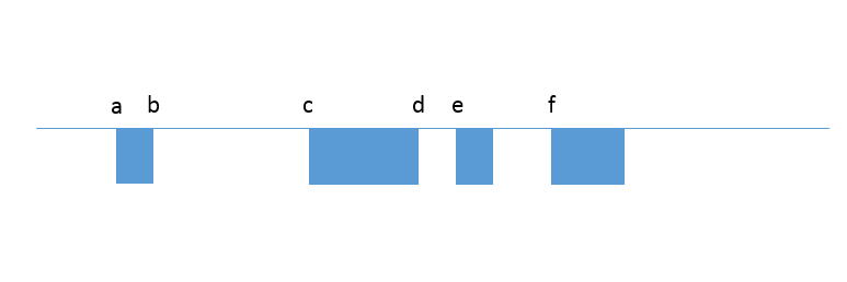 |
| A typical pulse scheme |
But using pulseIn(irpin, LOW) directly afterwards jumps over one pulse, because the low pulse already started. In the scheme on the right we see a pulse, x is the time axis. at the beginning we are at level 1(HIGH). Opening the pulseIn(irpin, HIGH) function gives us the length between b and c - we jump over our first pulse that is between a and b, what is not really good, and that's why we normally use the pulseIn(irpin, LOW) function at the beginning. But let's assume we started with the HIGH method, so now we get the length between b and c. The microcontroller is slightly after position c now, because it waited for the high pulse to end and additionally saved the pulse length for later. Next we want the length between c and d. But using pulseIn(irpin, LOW) now just gives us the length of the pulse beginning at e - because we are already in the LOW-phase and additionally, the pulseIn(irpin, LOW) function waits until a new low pulse begins - we jump over one full pulse, as said at the beginning.
So what we do is we use the micros() command to solve this problem. This function gives us the time in microseconds our program is running on the Arduino - at every place we want. So using this function we can save the time where the Arduino actually is executing our commands. So now we do not use the pulseIn(irpin, LOW) and pulseIn(irpin, HIGH) functions in a loop, we only use pulseIn(irpin, LOW) and directly afterwards the micros() command. The output times are stored in a matrix - a list with positions we can later on read out and store values in. To come back to the pulse sequence from above, we first get the length between a and b, the time-position of b, then the length between c and d, and the time-position of d, and so on. The high pulses are afterwards calculated, so for the first HIGH pulse we calculate d minus b minus length (a to b). That's it.
 |
| Arduino, IR sensor and IR LED |
Some other things are implemented to make the output more beautiful, understandable and usable, like comma-separated values (CSV) when we later want to build up our own remote by copying the received pulse sequence. The ende integer is used to throw away unneeded values and get out of the procedure when no more LOW pulse is measured, then the pulseIn() function returns zero after some time. The measurement always switches between HIGH and LOW pulse measuring, and in the output you can see the first (low) pulse cannot be measured using the HIGH method, of course.
You can download the .ino program here.


Beim Umgang mit Mikrocontrollern und Sensoren zählt Präzision. Auch in wissenschaftlichen Arbeiten ist Genauigkeit entscheidend – http://bachelorarbeitenschreiben.de/ hilft, komplexe Inhalte klar zu strukturieren und präzise darzustellen, damit Ergebnisse überzeugend sind.
AntwortenLöschen